|
2 Comments
This is for permanent magnet type 3 phase alternators which generally are the most common type used in the Power Sports Industry. Using a Volt meter on DC Volts check at the battery post with the engine running. You should have at least 13.5 volts just off idle up to a max of 14.75 volts at higher rpm. If you do not see this follow the steps below. If you do then need to check with an amp meter hooked up inline between the positive battery cable and battery. Turn the key on and check to see if the amp meter reads negative. If it doesn't flip your leads. Now check to make sure you see a positive number when the engine is revved up over idle. If not, follow the steps below. If both these checks are good then the charging system is working and you may have a suspect battery. Step 1 - Locate the three wires (usually yellow or white) coming from the stator in the engine. You will find a connector on this wire. Disconnect this and check for resistance between each pair of wires. (3 checks). You should have a approximately 1 ohm resistance. Pass - 1 ohm on each pair and no continuity to ground. Fail - High resistance or continuity to ground. Step 2 - Next check for AC voltage between each pair of wires as above with the engine running at approx 3,500 rpm. Pass - You have over 50 volts between each pair and the 3 checks are within a couple of volts. Fail - You have low voltage or the voltage varies between each pair. If you pass these tests then the stator is good. You then need to move on to checking the Regulator/Rectifier or possible damaged or corroded connections or wiring. 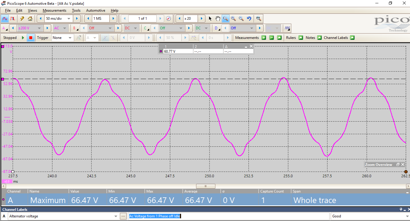 Thought I would share this as this question came up today. I have customers that want to order a high output ignition coil sometimes to get a "hotter spark" for better performance. What they do not realize is that in almost all cases on a stock or evenly slightly modified motor it will not make any difference. The advantage to a high output cool is it's potential to supply a higher voltage if the motor demands it because of its state of tune. Factors that can cause a higher spark energy are the spark plugs gap, compression ratio, air/fuel ratio....etc. Stock or modified motors will generally never come close to exceeding the stock coils potential. Save your money. See the waveform below from a Suzuki GSXR that I captured using our Pico Oscilloscope.As you can see the peak voltage requirement is not even 9,000 volts when revving the engine. It is obvious that a 30,000 Volt coil is overkill and not necessary for peak performance. 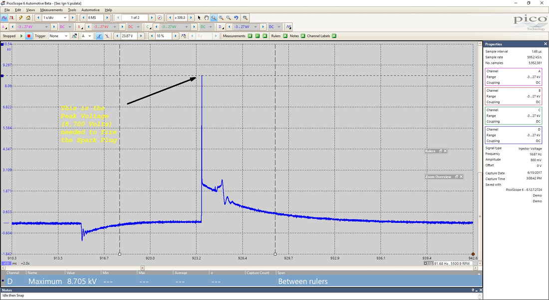 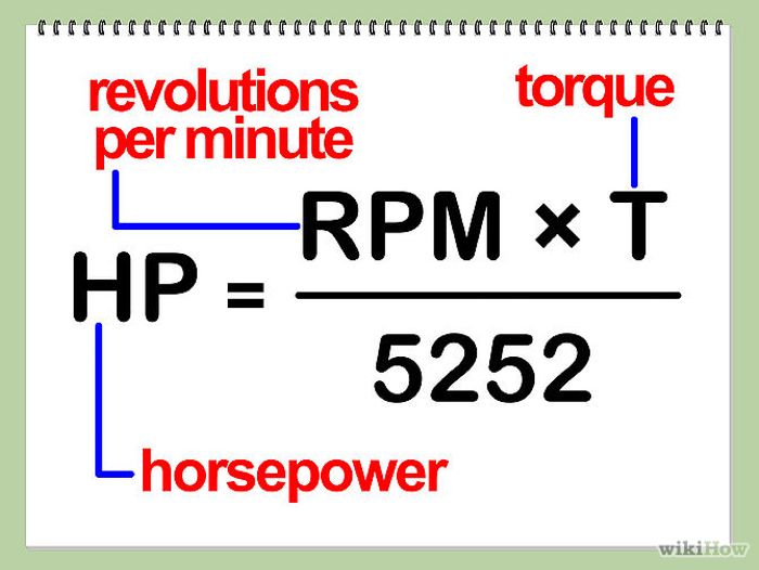
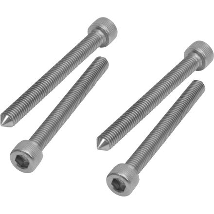
BMEP refers to the term "Brake Mean Effective Pressure" and is a theoretical but simple way to compare the performance of similar engines as well as evaluating "Performance Claims" of parts and or engine builders. A engine designed for reliability that is naturally-aspirated and gasoline-fueled would normally have a BMEP of under 205 psi. Anything above that would require a very expensive engine development program. (ie: WSB, Formula 1) The formula for BMEP (psi) = 150.8 x TORQUE (lb-ft) / DISPLACEMENT (Cubic Inches). Looking at our example above and plugging in the numbers - The 200HP is at the rear wheel so we need to add a very reasonable 15% on top because BMEP is calculated at the motor. So that means 230HP peak at the engine at aprox 12,000 rpm which calculates back to 100 ft lbs of torque at 12,000 rpm (HP = Torque X Rpm / 5252. So BMEP of thi phantom engine would be 150.8 x 100 / 61 = 247psi. Somebody is lying.... If we Plug in the numbers for a stock R! as pictured in the Dyno graph below we can see it is a much more reasonable figure of aprox 190 psi. If we use a BMEP number of 205 psi @ say 12,000 rpm you can see that a realistic potential HP for a modified R1 would work out to 83ft lbs of torque or 190 Hp and that is at the motor! Rear wheel would be aprox 15% less at 162hp.  A lot of the non sport bikes models are under sprung from the factory. ie:cruisers You actually have 2 springs, the fork spring and a "air spring" from the trapped air space in the fork. This air spring as the fork compresses is very progressive in its action.i f your fork rides low in the stroke because of too soft a fork spring you will be riding in the firmer part of the air spring. If the correct stiffer fork spring is installed the fork will sit up higher in the stroke and consequently sit and operate in the much softer part of the air spring. This will make the fork action plusher as well as help stability and cornering . This is also why you do not want to run air pressure in your forks if so equipped as this exaggerates the progressive nature of the air spring. If replacing fork springs you want a "straight rate" not a progressive rate as you do not want to add any more to the progressive nature of the air spring. 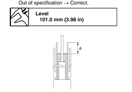 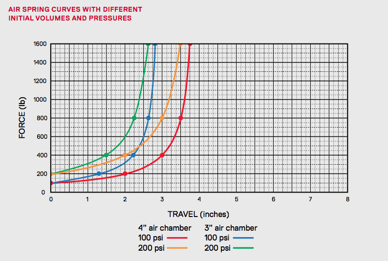 Yes there is. The circlip opening should be either at the top or bottom. The reason is even though it's small the clip has mass. If the clip opening was at the sides when the piston stops at either the top or bottom of its stroke the clip will want to keeping moving (a body in motion wants to stay in motion)..it could possibly compress and come out of the groove. 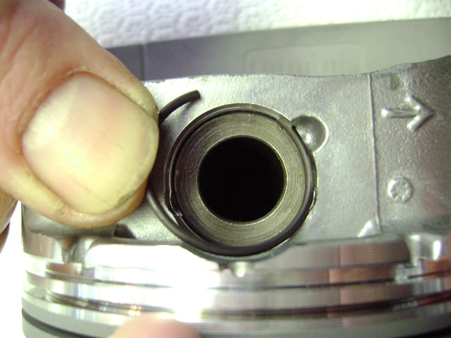 You may notice in the first picture that the far left Intake camshaft holder is marked with an E1. This holder unfortunately should be on the exhaust side. This R6 engine was bought by a customer off Ebay to replace his damaged motor. He brought it in for us to install and suggested taking the valve cover off to inspect and check the valve clearance before installing. This is one of the reasons why I would always recommend and rather rebuild a motor than buy used. This motor ran like this and ultimately caused some damage to the cam and journal. Lesson- you have no idea what your getting when you buy used. Left Picture - Sometimes when mounting accessories with multiple attachments points it's a real pain to get a few of the bolts started if things don't quite line up. I trick I use is to thread a nut on the bolt & grind at least a 7mm long taper on the end down to a dull point. (a new longer bolt may be needed). Thread off the nut. Now when you insert the bolt, push to help align it with the hole while turning.
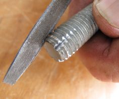
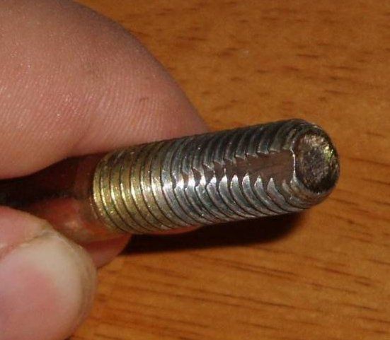
Right 2 Pictures - If you have a hole with slightly damaged or dirty threads and you do not have the correct tap you can make up a cheap thread chaser from a bolt of the correct size. Using a file you can cut a longitudinal V channel at the end of the bolt. You need to ensure that the 90 degree edge is leading in the direction of travel. The back edge of the travel gives the chips somewhere to go. This is cylinder head where the valve guide has become loose in the head and the guide hole no longer provides enough of an interference fit to securely hold the guide. Using our new State of the Art Rottler Seat and Guide machine we repair this by machining up a centering sleeve and using this to allow us to ream a larger concentric hole. We then custom machined a new guide from Ampco 45 that gives us a .04mm interference fit. The guide is cooled and the head warmed up to install the the new guide. After sizing the id to fit the valve we will recut the valve seat.
|
AuthorI have been involved in mechanics and motorcycling from a young age. I formed Cycle Improvements in 1981 and still have the same passion to learn today as when I started. Hope you find this blog interesting and educational. Archives
March 2021
Categories |
 RSS Feed